Fully Lined Ceramic Ball Valve
High-performance structural ceramic lining for strong corrosion, severe abrasion and particle-laden slurry service.
Product Overview
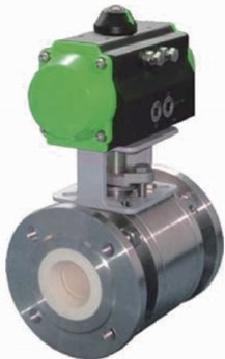
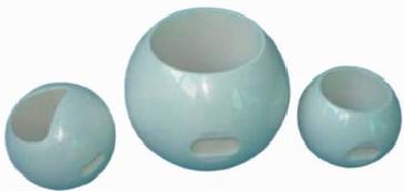
Fully lined ceramic ball valves use high-performance structural ceramics, primarily high-purity toughened zirconia, for the ball and all wetted lining surfaces. They deliver stable service and longer operating life than conventional metal hard-seated ball valves in strong acids, strong alkalis, slag powder, solids and slurry, whether used for isolation or control.
The valve uses a three-piece, flanged body and is available from PN10 to PN160 and ANSI Class 150 to 900, in sizes DN15–DN300 (½–12 in). DN15–DN100 (½–4 in) valves generally use a floating ball, while DN125–DN300 (5–12 in) valves use a trunnion-mounted ball. The ball is zirconia ceramic and the seat and body lining are ≥99% zirconia ceramic. Special materials, face-to-face dimensions and flange dimensions can be engineered to order.
Components and Materials
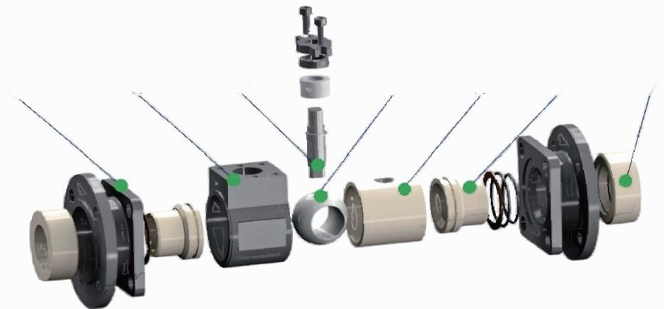
| No. | Component | Material |
|---|---|---|
| 01 | Valve Body | A105N, SS304, SS316, SS304L, SS316L |
| 02 | Body Connector | A105N, SS304, SS316, SS304L, SS316L |
| 03 | Nut | A194-2H/8 |
| 04 | Stud | A193-B7/B8 |
| 05 | Flange Lining | Structural Ceramic |
| 06 | O-Ring | Fluorocarbon Rubber / Silicone Rubber |
| 07 | O-Ring | Fluorocarbon Rubber / Silicone Rubber |
| 08 | Valve Seat | Structural Ceramic |
| 09 | O-Ring | Fluorocarbon Rubber / Silicone Rubber |
| 10 | Valve Ball | Structural Ceramic |
| 11 | Body Lining | Structural Ceramic |
| 12 | O-Ring | Fluorocarbon Rubber / Silicone Rubber |
| 13 | Gasket | PTFE |
| No. | Component | Material |
|---|---|---|
| 14 | Bushing | SS304/SS316L/Hastelloy C276 |
| 15 | Packing | Graphit/PTFE |
| 16 | Packing Gland | SS304 |
| 17 | Valve Stem | 17-4PH/SS316/Hastelloy C276 |
| 18 | Belleville Spring | SS304 |
| 19 | Packing Gland Flange | A351 CF8 |
| 20 | Stud | ASTM A193-B7/B8 |
| 21 | Nut | ASTM A194-2H/8 |
| 22 | Bolt | SS304 |
| 23 | Mounting Bracket | A351 CF8 |
| 24 | Stop Plate | SS304 |
| 25 | Handle | SS304 |
| 26 | Screw | Stainless Steel |
Performance
Key Performance Features
The three-piece flanged design provides installation flexibility. Flange dimensions and face-to-face length can be customized so the valve can connect directly to the customer pipeline without field modifications, reducing installation cost.
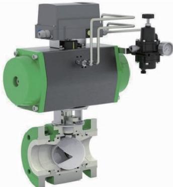
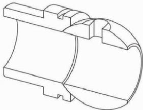
Inside the body, every wetted component—including the ball, seat, body lining, flange lining and stem—is designed and assembled to keep the metal shell isolated from the process medium. This protects the body from corrosion, erosion and abrasion. Precision-ground ceramic ball and seat surfaces achieve ANSI Class VI shutoff. Structural ceramic hardness and low surface roughness reduce friction and operating torque. The actuator bracket conforms to ISO 5211, and quarter-turn electric or pneumatic actuators can be mounted through interchangeable brackets selected for the actuator interface. Because ceramic ball valves require less torque than soft- or metal-seated valves of the same size, contact our team for proper actuator sizing.
Excessive actuator output torque can damage the ceramic valve ball.
Corrosion Resistance
High-purity zirconia ceramic (ZrO₂), formed by cold isostatic pressing and high-temperature sintering, is chemically stable against most organic solvents and inorganic process media, except concentrated sulfuric acid and hydrofluoric acid. It does not contaminate the process and maintains its physical and chemical properties during long-term service in strong acids, strong alkalis and highly corrosive slurries.
Sealing and Flow Characteristics
The ceramic ball and seat form a precision-ground spherical seal with a surface roughness of Ra 0.1–0.4. High ceramic hardness and self-lubricating behavior support zero leakage (Class VI) while keeping operating torque well below comparable metal- or soft-seated ball valves, preventing torque-related ball damage.
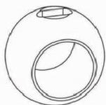
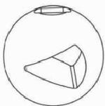
The ball and seat mate without clearance, preventing solids from lodging between the sealing surfaces and causing sticking. O-port and V-port ball options are available. The O-port ball is primarily used for isolation; the V-port ball provides equal-percentage control for applications that require accurate, stable flow regulation. Its V-port can also shear particles and fibers and self-clean the sealing surfaces. Where control accuracy is less demanding, the O-port ball can also be used for throttling.
Abrasion Resistance
Zirconia structural ceramic has a hardness of approximately HRA 85, well above stainless steel and hard alloys. The high hardness and strength of the ceramic trim give fully lined ceramic ball valves excellent abrasion and erosion resistance in pneumatic powder conveying and slurries containing hard solids.
Fully lined ceramic hard-seated ball valves have demonstrated reliable performance in severe, high-abrasion and high-erosion lines across steel, metallurgy, petrochemical processing, mineral processing, thermal power, pulp and paper, and polysilicon operations.
| Valve Size | Cvmax. | |
|---|---|---|
| O-Port | V-Port | |
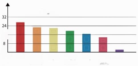
| 1/2″ | 15 | 8 |
| 3/4″ | 34 | 18 |
| 1″ | 45 | 18 |
| 11/4″ | 63 | 35 |
| 11/2″ | 114 | 87 |
| 2″ | 227 | 122 |
| 21/2″ | 316 | 175 |
| 3″ | 482 | 240 |
| 4″ | 810 | 406 |
| 5″ | 1140 | 485 |
| 6″ | 1900 | 610 |
| 8″ | 2350 | |
| 10″ | 3870 | |
| 12″ | 5200 | |
Technical Parameters
Size Range
·DN15,20,25,32,40,50,65,80,100,125,150,200,250,300
·NPS 1/2″,3/4″,1″,11/4″,11/2″,2″,21/2″,3″,4″,5″,6″,8″,10″,12″
Pressure Rating Range
·PN 10,16,25,40,63
·ANSI Class150,300,600
Face-to-Face Length
Per GB/T 12221 and ASME B16.10.
Custom face-to-face lengths are available on request.
Operating Temperature Range
·-30°C to 200°C (standard design)
·-30°C to 500°C (high-temperature design)
Shutoff Rating
·ANSI B16.104 Class VI (zero leakage)
Material
·Body — A105N, SS304, SS316, SS304L, SS316L
·Trim — zirconia ceramic ZrO₂
·Stem — 17-4PH, SS316, SS316L or Hastelloy HC276
·Packing — graphite or PTFE
Installation Dimensions
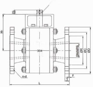
| DN | NPS | (GB/T9113 PN16,RF) | (ASME B16.5 Class150,RF) | ||||||||||||
|---|---|---|---|---|---|---|---|---|---|---|---|---|---|---|---|
| L | φD | φC | n-d | φR | T | F | L | φD | φC | n-d | φR | T | F | ||
| DN15 | 1/2″ | 108 | 95 | 65 | 4-M12 | 46 | 14 | 2 | 108 | 90 | 60.3 | 4M12 | 34.9 | 11.6 | 2 |
| DN20 | 3/4″ | 117 | 105 | 75 | 4-M12 | 56 | 16 | 2 | 117 | 100 | 69.9 | 4M12 | 42.9 | 13.2 | 2 |
| DN25 | 1″ | 127 | 115 | 85 | 4-M12 | 65 | 16 | 2 | 127 | 110 | 79.4 | 4M12 | 50.8 | 14.7 | 2 |
| DN32 | 11/4″ | 140 | 140 | 100 | 4-M16 | 76 | 18 | 2 | 140 | 115 | 88.9 | 4-M12 | 63.5 | 16.3 | 2 |
| DN40 | 11/2″ | 165 | 150 | 110 | 4-M16 | 84 | 18 | 3 | 165 | 125 | 98.4 | 4-M12 | 73 | 17.9 | 3 |
| DN50 | 2″ | 178 | 165 | 125 | 4-M16 | 99 | 20 | 3 | 178 | 150 | 120.7 | 4-M16 | 92.1 | 19.5 | 3 |
| DN65 | 21/2″ | 190 | 185 | 145 | 4-M16 | 118 | 20 | 3 | 190 | 180 | 139.7 | 4-M16 | 104.8 | 22.7 | 3 |
| DN80 | 3″ | 203 | 200 | 160 | 8-M16 | 132 | 20 | 3 | 203 | 190 | 152.4 | 4-M16 | 127 | 24.3 | 3 |
| DN100 | 4″ | 229 | 220 | 180 | 8-M16 | 156 | 22 | 3 | 229 | 230 | 190.5 | 8-M16 | 157.2 | 24.3 | 3 |
| DN125 | 5″ | 356 | 250 | 210 | 8-M16 | 184 | 22 | 3 | 356 | 255 | 215.9 | 8-M20 | 185.7 | 24.3 | 3 |
| DN150 | 6″ | 394 | 285 | 240 | 8-M20 | 211 | 24 | 3 | 394 | 280 | 241.3 | 8-M20 | 215.9 | 25.9 | 3 |
| DN200 | 8″ | 457 | 340 | 295 | 12-M20 | 266 | 24 | 3 | 457 | 345 | 298.5 | 8-M20 | 269.9 | 29 | 3 |
| DN250 | 10″ | 533 | 405 | 355 | 12-M24 | 319 | 26 | 3 | 533 | 405 | 362 | 12-M24 | 323.8 | 30.6 | 3 |
| DN300 | 12″ | 610 | 460 | 410 | 12-M24 | 370 | 28 | 4 | 610 | 485 | 431.8 | 12-M24 | 381 | 32.2 | 4 |
Note: Dimensions shown are standard references. Face-to-face length and flange dimensions can be customized to customer requirements.